Blinking Lights with NodeMCU
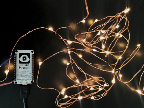
Diwali, the festival of lights, is around the corner so I decided to take the hardware box out and have some fun! In this blog post, we will setup a NodeMCU (v1.0) on a linux box and then use the digital pins of the NodeMCU to blink some led lights or rather led strips.

Things that we’d need:
- NodeMCU v1.0
- 5v powered led strip - the power rating here is important because we will power the led strip using NodeMCU
- Few connecting wires
- Digital Multimeter
Let’s begin:
-
Let’s begin by setting up the NodeMCU. You’d need a micro-USB data cable and connect it to your computer.
A quick note here: the cable has to be a micro-USB data cable and not a charging cable because charging cables sometimes do not include data lines and that’d make your system power the NodeMCU but won’t recognize it for programming.
-
Setup CP2102 drivers so that your computer can recognize the NodeMCU. My operating system (Ubuntu 20.04) already includes these drivers so I didn’t need to do this step. The drivers can be downloaded from here (go to downloads tab and this may required signing up): https://www.silabs.com/developers/usb-to-uart-bridge-vcp-drivers
-
Install Arduino IDE: https://www.arduino.cc/en/software/
-
Setup Arduino for NodeMCU development:
-
Go to File > Preferences > Additional Board Manager URL and add this URL in the input field:
http://arduino.esp8266.com/stable/package_esp8266com_index.json -
Go to Tools > Board > Board Managers and search for ESP8266 by ESP8266 community and add it
-
Go to Tools > Board > ESP8266 > NodeMCU v1.0
-
Ensure that the NodeMCU microUSB cable is plugged into the system and then go to Tools > Port > Select your NodeMCU port here. This was
ttyUSB0for me. Ensure the NodeMCU is detected by using commands likelsusbanddmesg -wto watch for activity on the USB port
-
-
Once connected, let’s begin programming. Start a new sketch with the following code:
// data 0 pin
#define LED D0

// setup for digital write
void setup(void)
{
  pinMode(LED, OUTPUT);
}

// turn the LED on and off
void loop()
{
  digitalWrite(LED, HIGH);
  delay(random(100, 1000)); // random delay
  digitalWrite(LED, LOW);
  delay(random(100, 1000)); // random delay
}
-
Compile and burn the sketch to NodeMCU and this should set the
D0to high and low after random time intervals. To quickly debug this, I connected a LED toD0andGNDusing a pair of connecting wires. -
In the following steps, we will connect the led strip to
D0andGND. The LED strip that I used runs on 5V power, using a USB adapter and we will use this fact, to power the entire strip using NodeMCU, which also emits 5V on it’s data pins. The LED strip uses enameled copper wire i.e. the two copper wires run in parallel and have a very fine, invisible insulation that prevents theVCCandGNDcables from touching and short-circuiting the entire strip. -
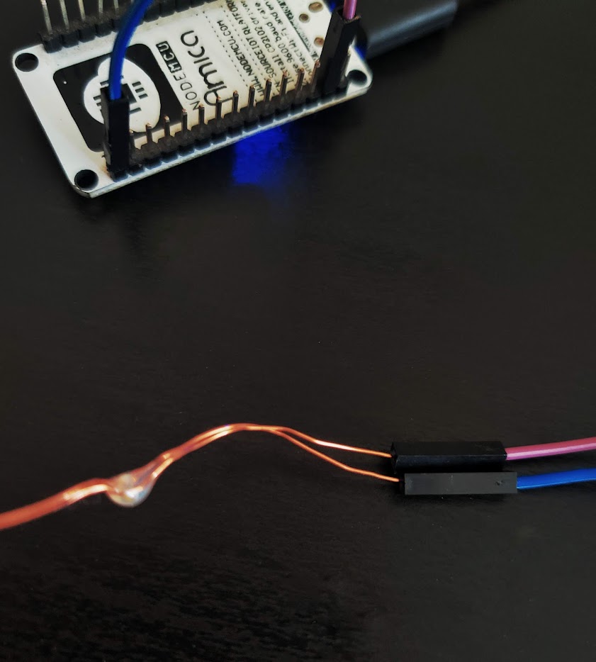
At the base of the LED string, identify and separate out the copper cables and the scrape-off the thin, invisible insulation using a knife or some sharp tool. At this point, make sure the two copper wires do not touch each other.
-
Use a digital multimeter to identify the live and ground wire. You can mark one of the cables using tape or color pens, to remember which one is ground wire. Now cut the cables at base and connect live and ground wire to
GNDandD0of the NodeMCU, using connecting wires.

-
Power-up the NodeMCU and you should’ve a blinking led strip.
-
Play with the code to change the blinking pattern or add another strip, to another data pin and make more blinking patterns.
Thanks for reading and Happy Diwali! :)